Draw the Qualitative Influence Lines
Influence line diagram (ILD) can be developed by the following ways;
(a) by independently applying a unit load at several positions on the structure and determining the structural response (reaction, shear, moment etc.) by applying the principles of statics. Tabulate these values and then plot the graph of load position(along x-axis) vs the structural response (along y-axis).
(b) write the equation for structural response due to a unit load at a distance 'x' by applying the principles of statics.
(c) Muller-Breslau Principle which gives qualitative influence lines.
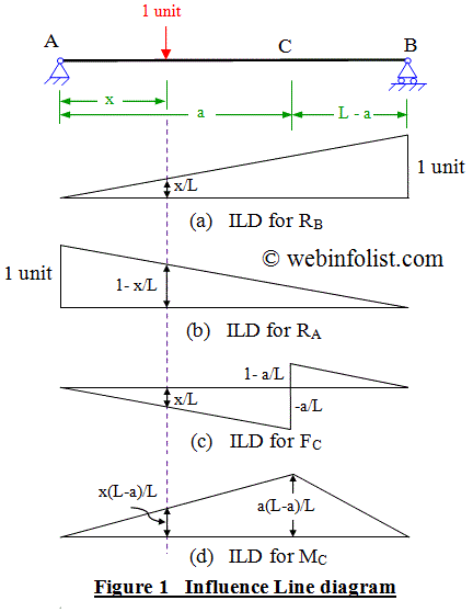
To explain the procedure of developing influence line we consider a beam of span L and apply a unit load at a distance x from the support A as shown in figure 1.
Influence line for Reaction
Calculating the reaction at supports we get;
R B = x/L(straight line equation)
R A = 1- x/L (straight line equation)
The influence line diagrams for R B is plotted in figure 1(a) which shows that the value of R B is x/L when the unit load is at a distance x from A and it would be equal to 1 when the unit load will be at B.
Similarly the ILD for R A plotted in figure 1 (b) shows that the value of R A will be 1 when unit load is at A and it would be equal to 1-x/L when the unit load is at a distance x from support A.
Influence line for Shear Force at a section
FC = -RB = - x/L ;when load is between A and C
FC = RA = 1- x/L ;when the load is between C and B
Influence line for Bending Moment at a section
MC = RB . (L-a) ; when unit load is between A and C.
MC = RA .(a) ; when unit load is between C and B.
MC = a (L - a) / L ;when unit load is at C.
The ILD for MC plotted in figure 1(d) clearly indicates these values.
It is evident from the above equations and their plot that influence line diagram is a straight line in all the cases.
Applications of Influence Line Diagram
You can also use the following calculators for Moving Load Analysis
Calculator for Moving Load Analysis for Maximum B.M. at a section of simple beam
Calculator for Absolute Maximum B.M. due to moving loads for simple beam
You can also select from the following links of solved examples to get prepared for your exams like GATE and GRE.

Draw the Qualitative Influence Lines
Source: https://civilengineeronline.com/str/ild-plot.htm